Precision Ergonomic Component
A client brought us a component they used every day and found uncomfortable, and asked us to reproduce and improve it in wood. We had full discretion over the design and the manufacturing method, and took it all the way from reference measurement to finished walnut parts, with a 3D-printed fit prototype along the way before we committed to final machining.
3D Model
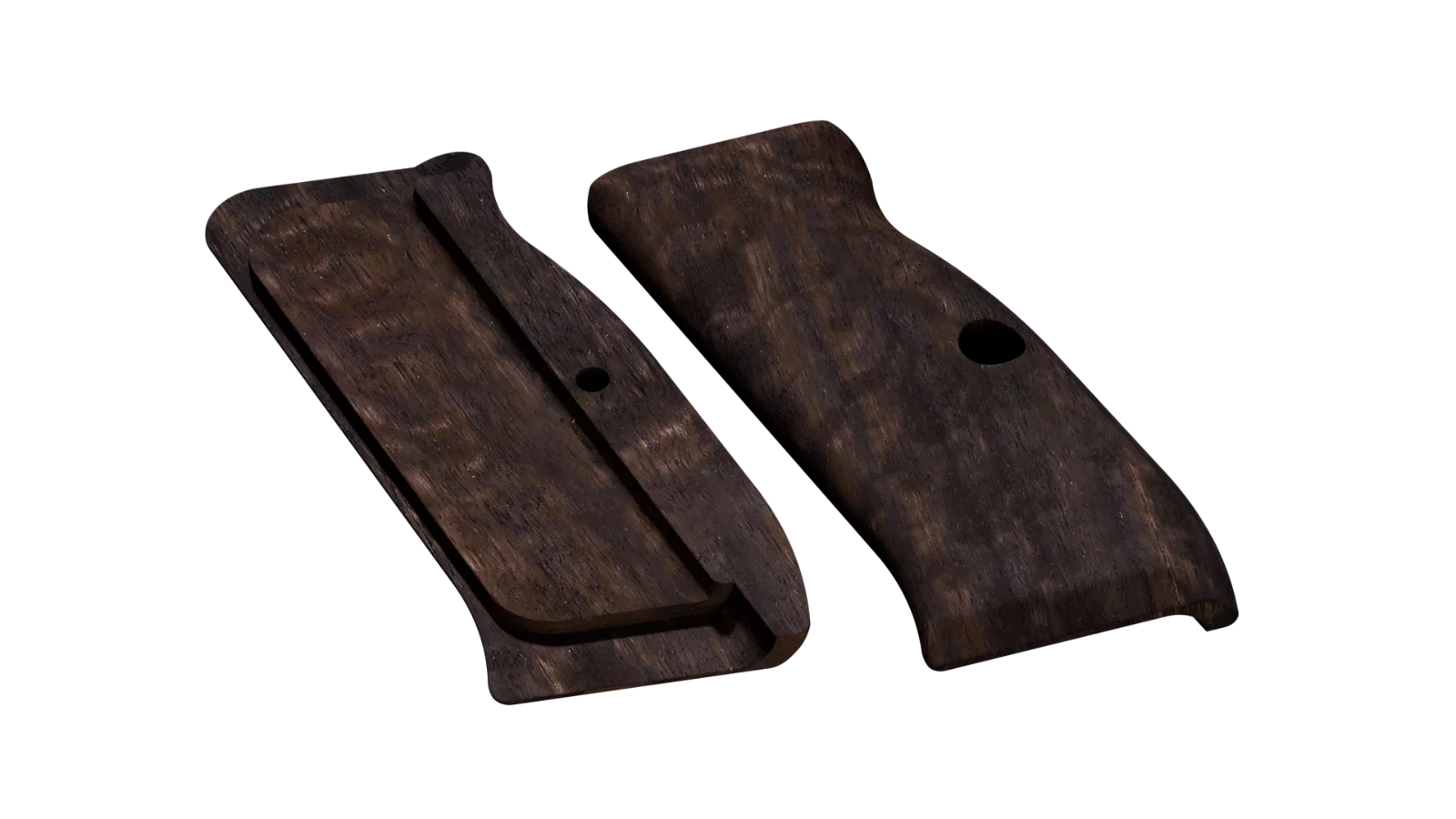
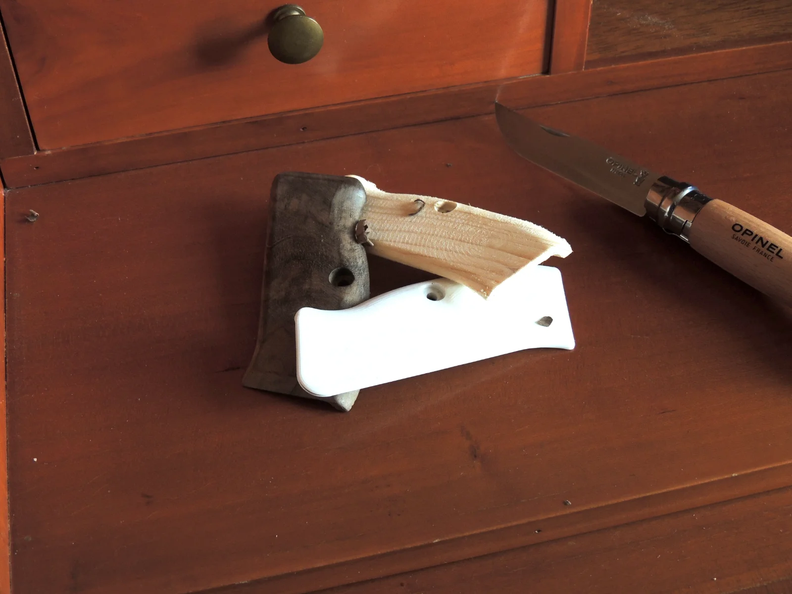
Working from the reference measurements of the original part, we rebuilt the geometry in CAD and reworked the areas the client found uncomfortable, reshaping the contact surfaces for a better fit in the hand. A photorealistic render went back to the client for sign-off before any material was cut. A 3D-printed prototype then let us confirm the fit and proportions in the real world, so we only committed the design to walnut once both the look and the feel were approved.
CAM
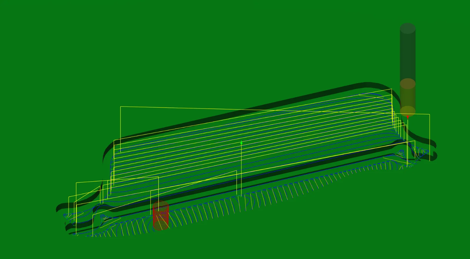
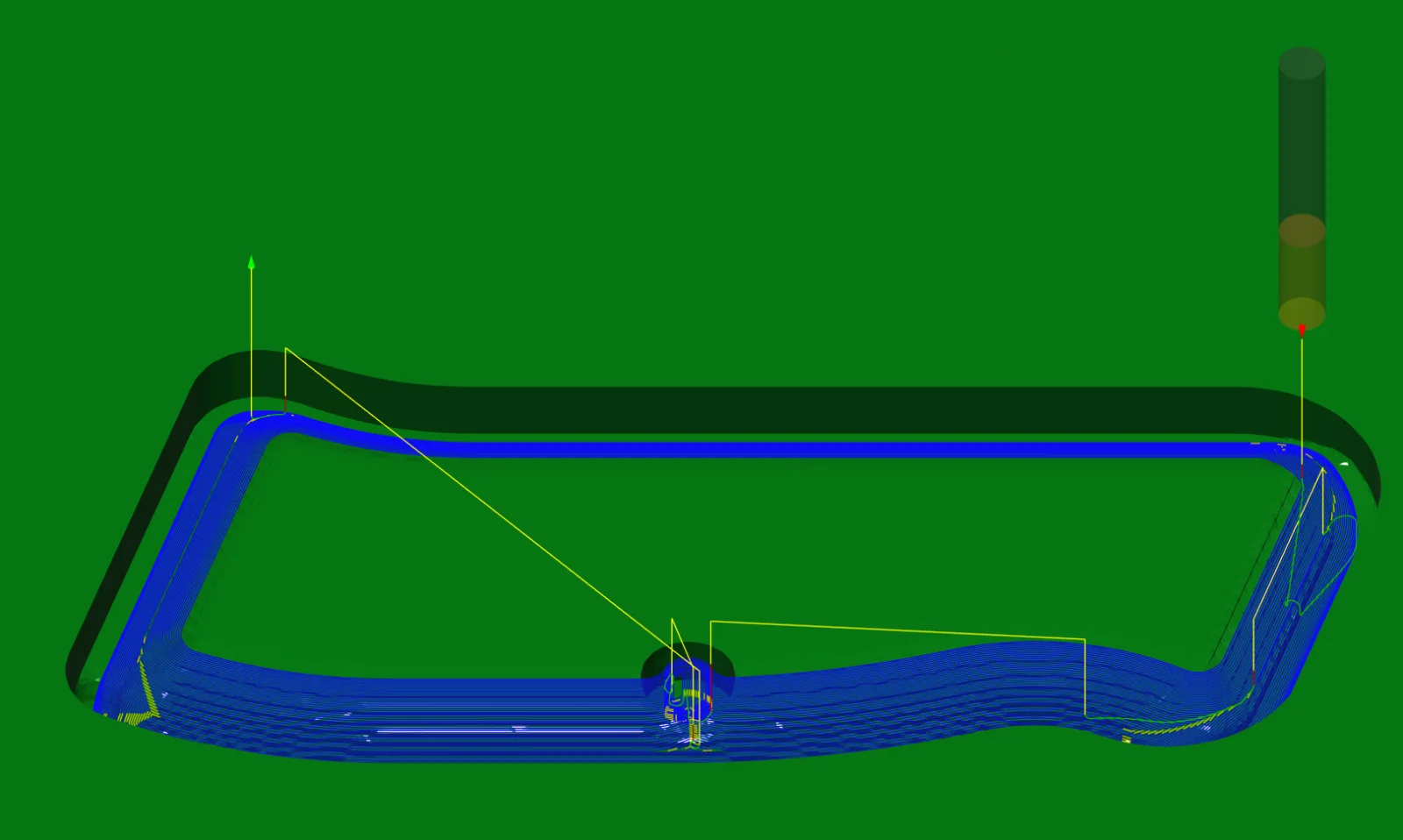
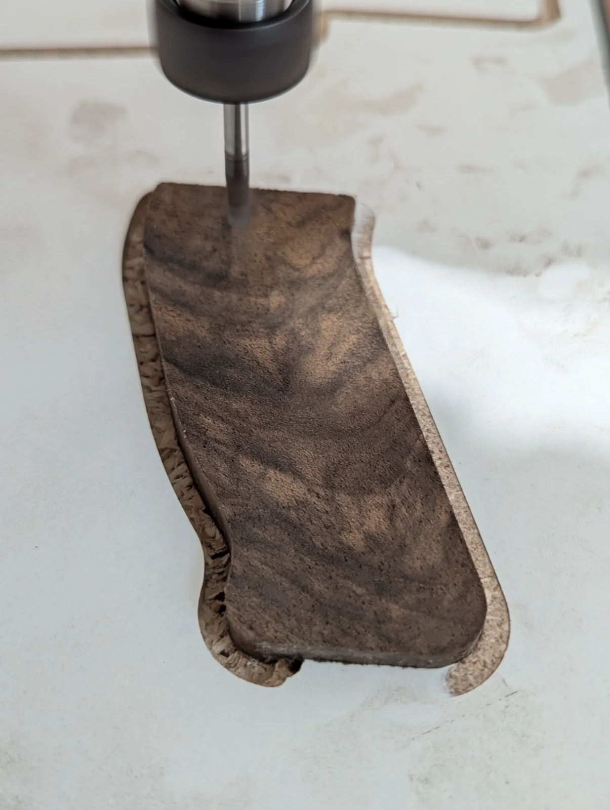
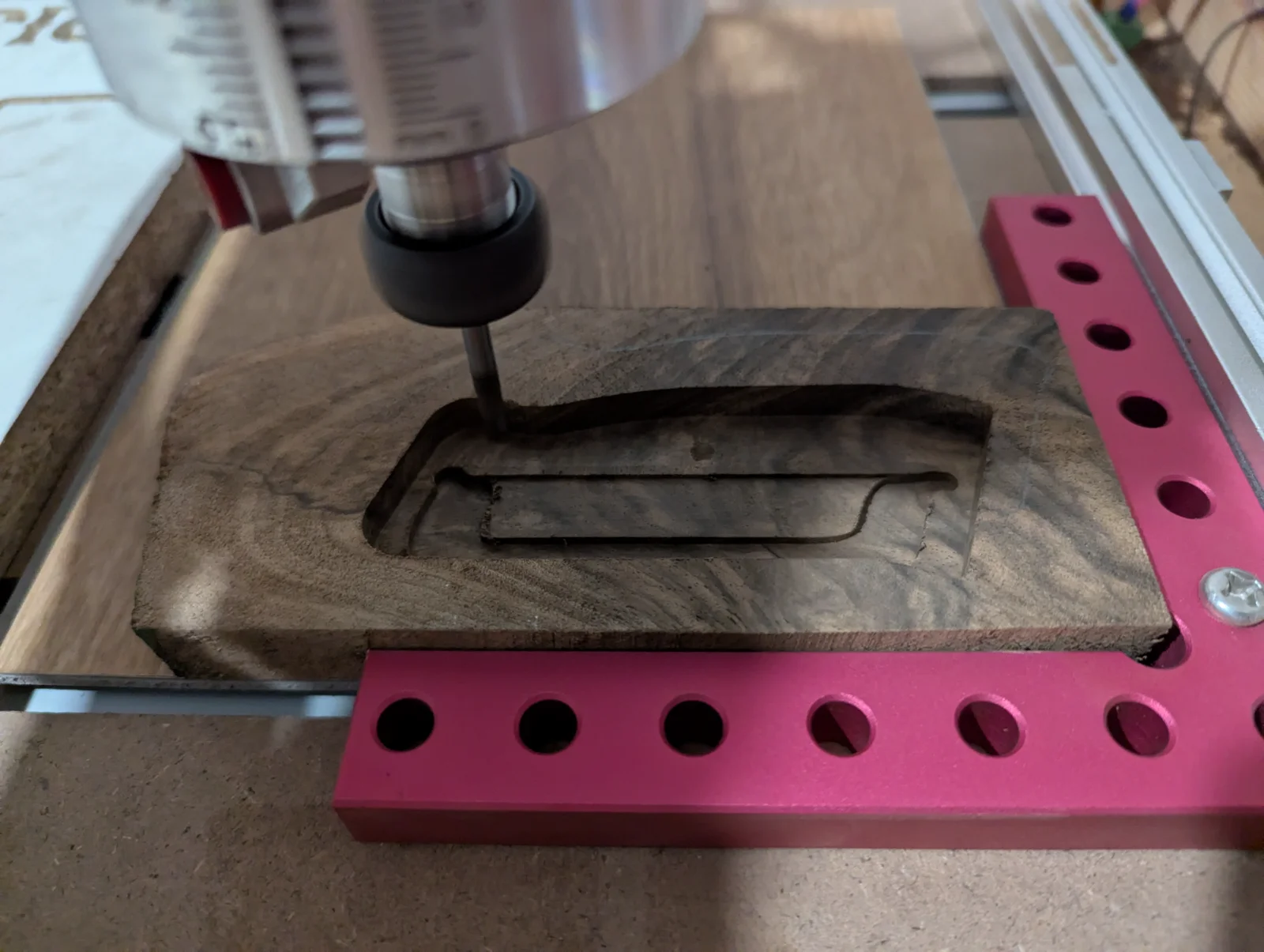
Because the part carries detail on both faces, we programmed it as a two-sided job. The first face was machined from flat stock, then the toolpaths for the reverse were referenced to a custom fixture: a negative cavity milled from the first-face geometry, so the part drops in and is held in exactly the right position and orientation. This let us cut the second face without losing alignment, keeping both sides true to the model.
CNC
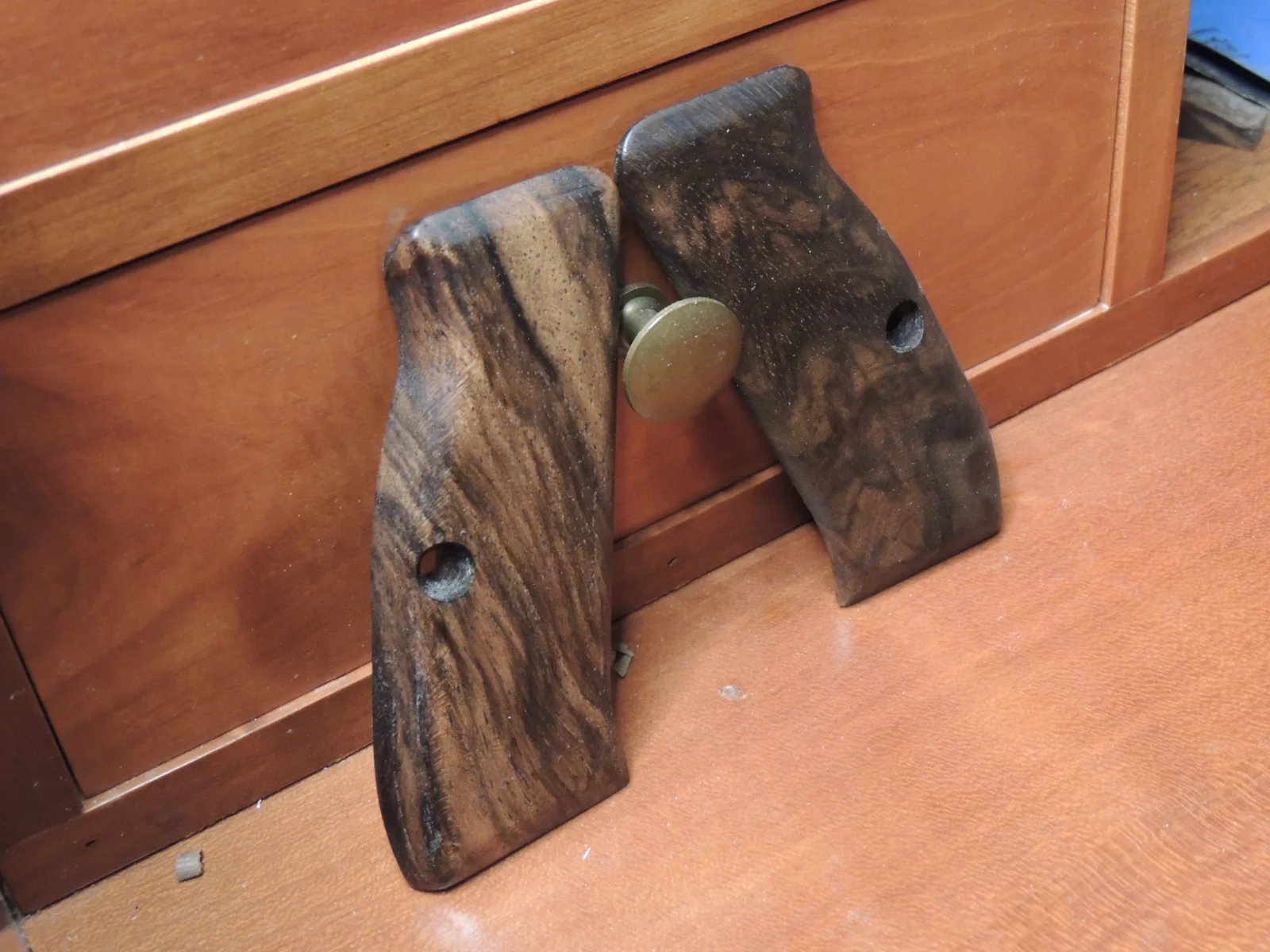
The component was machined from solid walnut on our in-house CNC router. With the first face cut, the piece was transferred into the fixture and flipped to machine the reverse, the cavity holding it steady against the cutting forces. Because both faces were referenced to the same model, the two halves of the form met cleanly along the part's edges, ready for hand sanding and a linseed-oil finish.
Finish
The challenge
Machining both faces of an ergonomic part to tight tolerances means flipping it mid-job without losing your reference. We machined a negative-cavity fixture from the first-face geometry, which locks the part precisely for the second operation. Both faces end up accurate to the original reference dimensions.